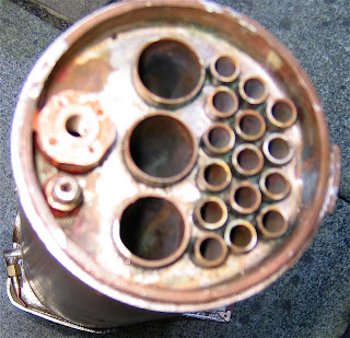
Work has progressed - the boiler is now complete. The assembly sequence I used was as described in Alex Farmers book on boiler making - and, as it happens, his was also a GWR boiler, although bigger.
As the assembly gets bigger, it always surprises me just how much heat it needs. I work outside, so can only work on wind-free ( and preferably dry) days. Also, I find it essential to use refractory bricks- without them, I'd never get up to temperature.
Even so, it needed two good sized gas torches, and occasional oxy-propane, to complete the assembly. I couldn't do this alone, and gratefully thank George and Russell for their help.

Where ever possible (and that's most of the time), we worked with pre-placed solder - its much easier than applying a stick, as it tends to melt - or at least sag - if you're not quick. We put rings of silver solder under the heads of all the rivet - stays in the firebox. As the solder flowed, each was grasped on the outside with pliers, rotated and pulled into place. This (I hope) helped the solder to penetrate. Also - and very important - old texts always advised reamed holes and minimum fit. Alex Farmer advises precisely drilled and chamfered holes to allow clearance for the solder to flow. Easyflow 2 type solder will fill a gap of a few thou, but not more, and does need a gap for capillary action to work. The pre-placed solder resulted in an excess of solder around the boiler, which is waste, and gives away the amateur status of its maker! - a small price to pay.

I fitted the firebox doorplate and backhead after the stays had been fixed internally. This made it very easy to work on the stays which are pretty inaccessible if you follow the traditional sequence of construction), but I was worried that it might be more difficult to fit these plates at such a late stage. In face, it was perfectly straight foreword - my only slight problem was that the rear foundation ring needed to be nearer to 5/16 than to the 1/4 inch specified in the drawings, so a new piece of copper was machined up to fit.

I made up plugs to blank all the bushes - in some cases, my blanking pieces were in fact the part machined finished components - minus their through -holes.
The boiler was tested - at 160 psi - twice its working pressure - and certified by the club boiler inspectors. Up to this point, I'd left all the stay - rivets t their original length, as, If I'd needed to redo anything major, the extra length is important to get the heat in.
So now they've been cut to length with a Dremmel (and lots of cutting disks) but it doesn't distort the stays the way cutters would.
I plan to re-tset it at 1.5 x pressure, to prove that I havn't compromised the seal on any of the stays.
I've been working on the cladding and false backhead. Older practice was to leave a 3 1/2 in gauge boiler painted but unclad, as far as I can see, with small fittings screwed directly into the boiler. I didn't fancy this one bit, and all my fittings will be attached to the cladding only. Also, I'll put a bit of thermal insulation between the layers - if only to protect the cladding from the stay heads! I remember doing heat transfer calculations a long time ago, and finding that it's the existence of an air gap that is the major factor in preventing heat loss, not its size.
Having tried the boiler between the frames, its now starting to look like a loco. My list of things still to do is only half a page!

Comments
I enjoy reading all the work you do. I might not understand it all but certainly can appreciate all the work you do on it..
Have a great week
I find it all very fasinating, but..alas I too don't understand it all. I guess that's the beauty of learning something new.